Power Strip
• 5 minutes readIt’s been a couple months coming now, but I’m nearing version 1.0 of my power strip! You may be asking a few questions now, like “what power strip?” Well, after feeling frustrated about having to walk across the room to turn off a lamp with an awkward off-switch, I decided to over-engineer a solution. Starting with a power strip I found on Amazon, I began by taking it apart and looking at what I had to work with.
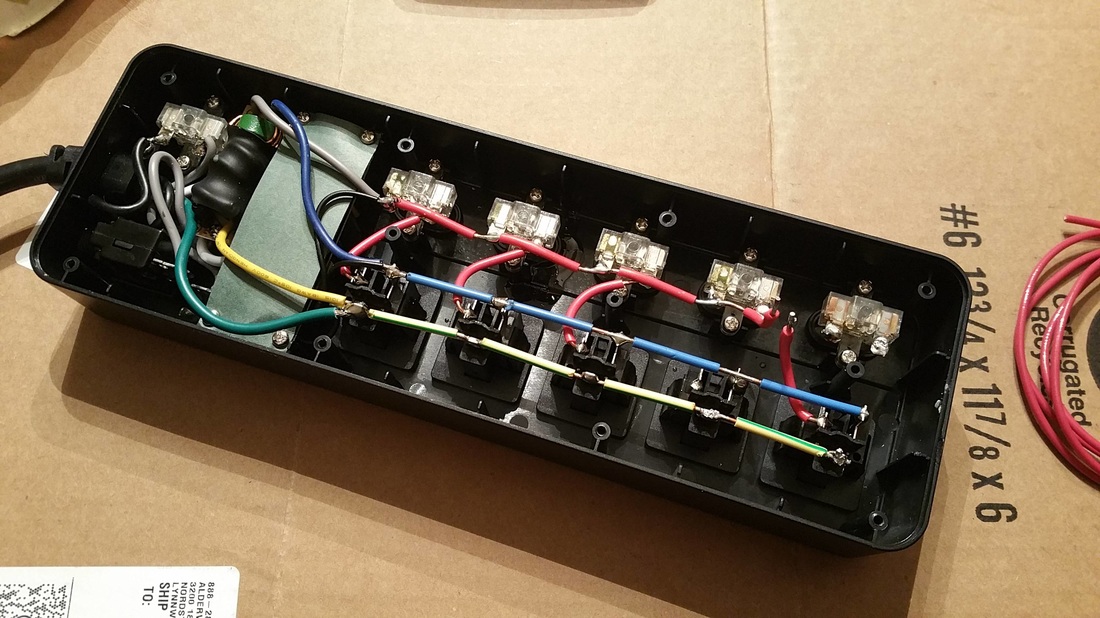
Fortunately, this strip happened to leave a lot of space to work with. I began by disconnecting the physical relays. I had a series of 8 electronically controlled relays, which I wired the outlets to after making sure I was properly handling mains-level current. With a few rudimentary python scripts in place, I had a working prototype! It looked like this:
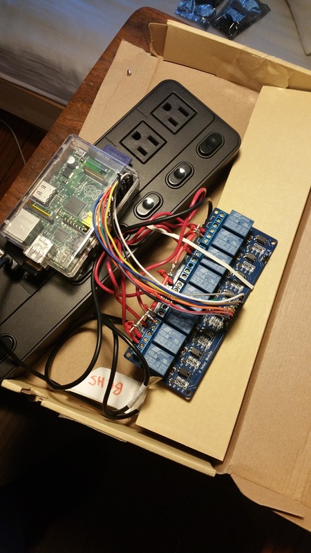
Yes, the rubber band was necessary
With that in place, I created a rudimentary Node server with a web view and used the strip that way for about a month. The server knew how to call ten python scripts, which would set the state of 5 GPIO pins to control the outlets. My webpage was incredibly minimalistic, and I only wrote buttons for the two outlets I was regularly using: a lamp and a space heater.{“ “}
It wasn’t until June that I picked the project back up for some major revisions. Since I knew that needed to present a final project for Galvanize, I decided to take everything to the next level. I wanted a more intelligent server and view, and a much tidier and more compact piece of hardware. For the server, I decided to continue using Node.js with Express, and I decided that React.js had a philosophy of state that would suit this project particularly well.
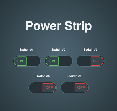
The first version of my new view
Using a switch animation I found on codePen (credited on the site and on github), I rebuilt the code in React and made it modular, creating one of the chief pieces of my view. Simple is better for an interface like this, and I wanted a UI that I would enjoy using from this point on. The next step was to take the power strip apart and do it better.
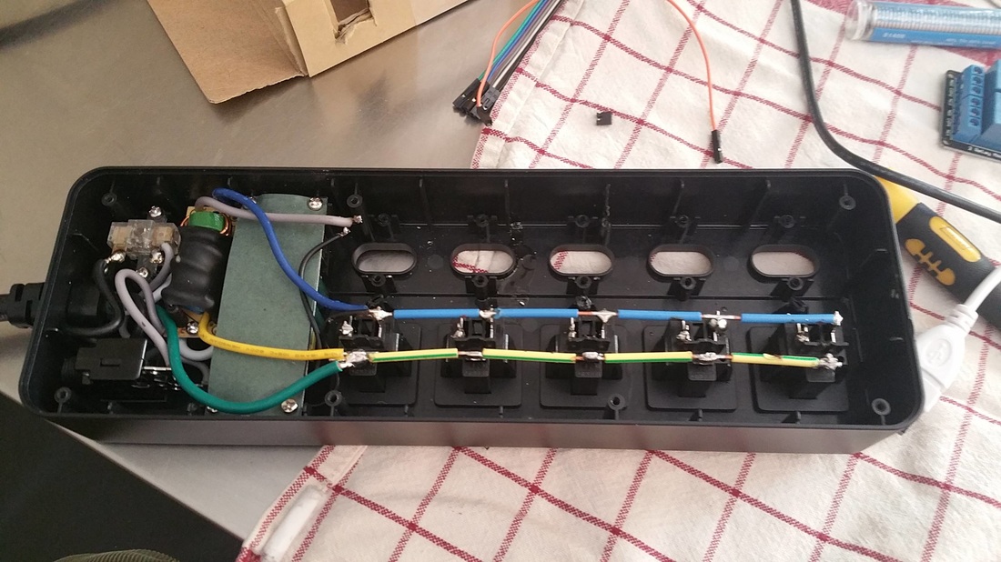
A new hope
This time, I removed all of the physical switches, and carved out the support structures that surrounded them. I would need all the space I could get inside the strip for my next step. 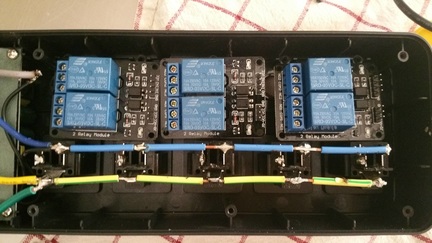
The new relays
With these relays off eBay, I was effectively able to split the larger block I had used the first time, and now the relays could control their respective outlets from inside the power strip. Space was tight, but I was committed to fitting everything within the original housing. 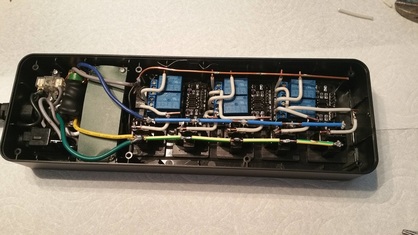
I make it look easy, right?
The next steps required a live wire that would connect to each of the relays, and for each relay to have another wire completing the circuit with the socket. These relays require a 5v vcc input, and default to being closed unless they also receive a signal on their input pins. So, by default, the relays break the circuit for each outlet unless they are told to connect it again.
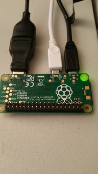
The new brains
While I had originally been using a Raspberry Pi 1B, I got a notification that there were a few Raspberry Pi Zeroes in stock on Adafruit. I picked one up for $5 and was thrilled to downsize my controller for the project. In the picture above, you’ll see that I manually soldered the GPIO pins on backwards for this device. It forced me to do some mental gymnastics for identifying pins, but it was necessary for how the pi would fit on the completed product.
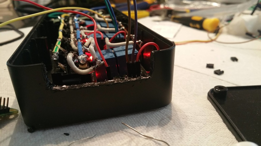
“Creative” use of a soldering iron
After creating an opening here on the side of the case, I had a space for the GPIO pins to point directly inside of the casing. Here, the Pi’s ports would be available and on display in case I ever needed to further configuration. This way, I wouldn’t need to open up the device constantly if something went wrong.

Connecting the backwards GPIO pins

Wiring up the relays

You can see Pi Zero bolted onto the back with spacers
After selecting and wiring up the pins, I faced a problem. The relays weren’t switching on. With dozens of potential points of failure, I was overwhelmed and gave up for the rest of the day. I’m sure all you hackers out there know the feeling.
The next day, after doing some research, I took a voltmeter to the pi and identified two points where I could directly have access to the full current of the usb input. It turned out that the pi was limiting the current as it passed through the circuit board, and not enough current was making it to the relays.
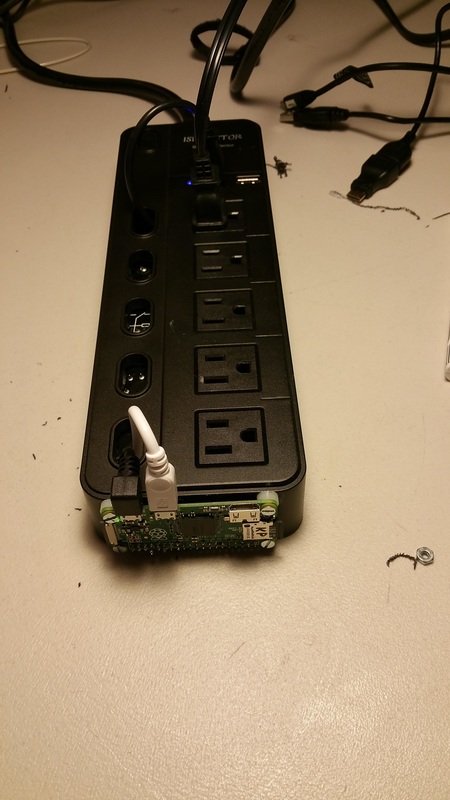
At long last, I was able to close the back of the strip, only to realize that I had wanted a couple cables to be directed inside the pi. The power cable was supposed to run through the inside, and the wifi dongle was meant to be housed inside the case. After cramming the cables through and re-soldering a couple broken connections, the cables all fit inside. With some minimal configuration to the server to update the GPIO pins, everything was working.
Since then, I’ve been working to improve the interface. I’ve added functionality for scheduling events, and I’m working on scheduling repeating events currently. My next steps will be to create a view to view, modify, or cancel events, and to host an external website so that the strip will not require special router configuration to be controlled from a different network connection
Thanks for checking this out! I’d love to answer any comments or questions you might have about this project.
You can check out my code at github.com/krpeacock/power_strip.